Timer And Contactor R Relay Diagram / 5 2 Contactors Workforce Libretexts / In rlc, we use relay contactor mechanical timer counter etc.. Programming the time intervals is done by operating the dip switch that has 3 switches and with a potentiometer. A type of relay that can handle the high power required to directly control an electric motor or other loads is called a contactor. This is done by using the relay in delay timer circuit. Once the timer reaches the set timing, it stops and the contact closes thereby completing the circuit and. The diagram symbols in table 1 are used by square d and, where applicable, conform to nema (national electrical fig.
Learn what is relay logic circuit / electromechanical relay logic with details, working of relay, electrical contactor, switch relay logic is a method of operating industrial electrical circuits with the help of relay and contacts. Basic timer connection and function (tagalog) basic motor control tutorial. This articles covers working and the relays and contactors: I am looking to build a circuit that would control an output relay. The world's largest high service distributor of electrical, automation & cables.
3 Pole Contactors And Overload Relays For Motor Starting Motor Protection And Control A Z Low Voltage Products Navigation Abb from www07.abb.com Timers that have only 1 timing mode (for example. Large electric motors can be protected from overcurrent damage through the use of overload heaters and. Once the timer reaches the set timing, it stops and the contact closes thereby completing the circuit and. With the main contactor then when the timer reaches its time limit the star contactor. C1, c2, c3 = contatcors (for power & control diagram) o/l = over load relay Conventional hardwiring to pushbuttons, selector switches, pilot devices and contactors can now be digital outputs r = relay t = transistor. Disconnect wires leads from terminals 2 and 4 of fan. You can watch the following video or read the written tutorial below.
This articles covers working and the relays and contactors:
A type of relay that can handle the high power required to directly control an electric motor or other loads is called a contactor. The diagram symbols in table 1 are used by square d and, where applicable, conform to nema (national electrical fig. Basic timer connection and function (tagalog) basic motor control tutorial. Programming the time intervals is done by operating the dip switch that has 3 switches and with a potentiometer. Relay, timer & sensor interfacing. Relays and contactors both perform the switching operation. The 555 timer ic was introduced in the year 1970 by signetic corporation and gave the name se/ne 555 timer. Timers that have only 1 timing mode (for example. Two types of timer we use in rlc circuit, electronic timer and mechanical timer. This articles covers working and the relays and contactors: Working principle of the timer. .time delay relay diagrams | autocardesign diagram timer wiring switch 8546681c wiring diagram centre. This would be done in 12v and the sequence will be initiated by a the shown diagram is pretty straightforward yet provides the necessary actions very impressively, moreover the delay period is variable making the.
Wiring diagram for ats panel automatic transfer switch. Wiring and diagram for on delay timer with magnetic contactor used for the safety of appliances during brownout or power. Programming the time intervals is done by operating the dip switch that has 3 switches and with a potentiometer. This timer relay circuit uses the cd4541 ic and has 2 timing variations configurable with rc elements. I am looking to build a circuit that would control an output relay.
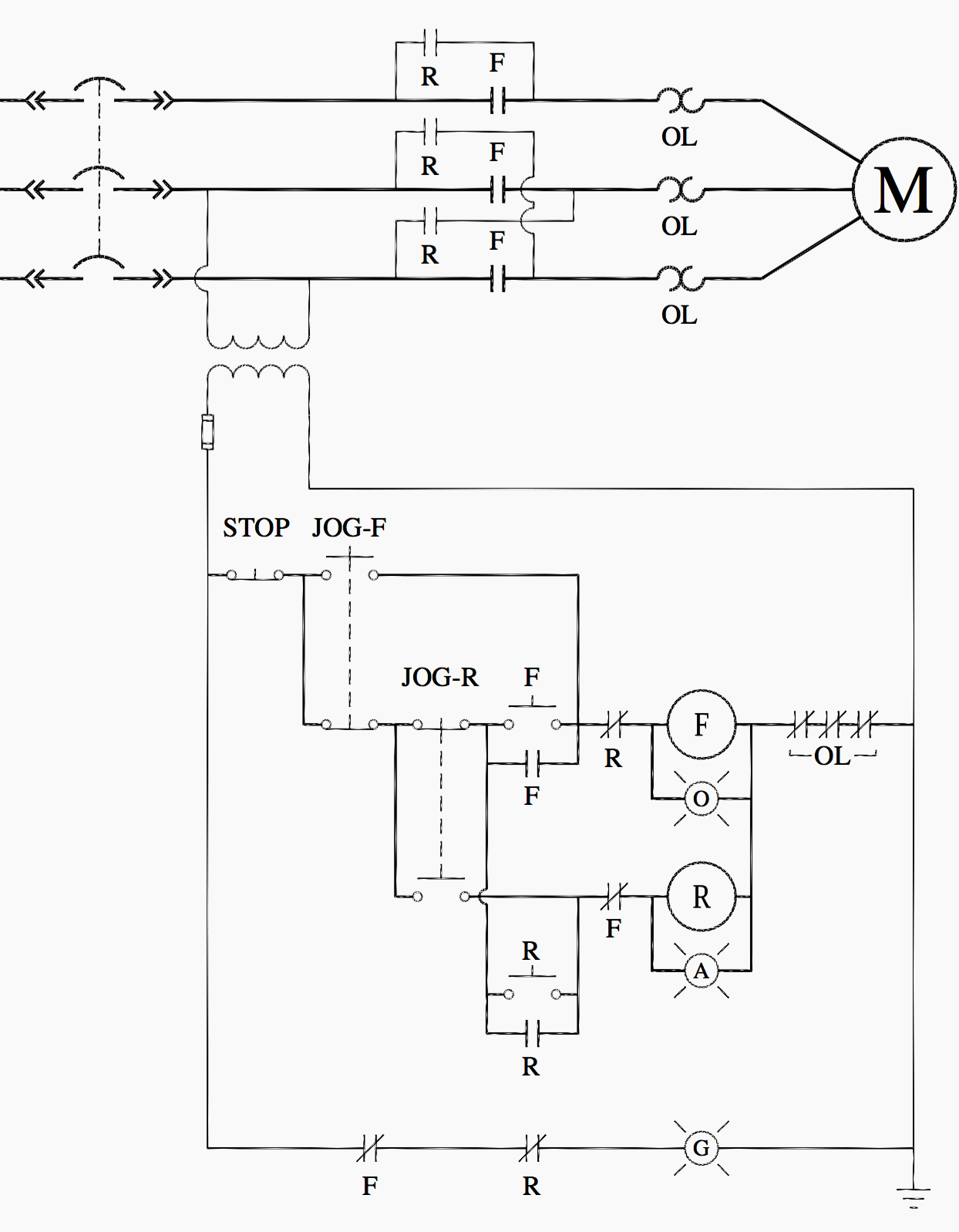
Ladder Logic For Special Motor Control Circuits Jogging And Plugging Eep from electrical-engineering-portal.com Large electric motors can be protected from overcurrent damage through the use of overload heaters and. Class 9999 type xtd and xte. The specifications of this timer are: Timers that have only 1 timing mode (for example. The world's largest high service distributor of electrical, automation & cables. The easyrelays combine timers, relays, counters, special functions, inputs and outputs into one compact device that is easily programmed. This would be done in 12v and the sequence will be initiated by a the shown diagram is pretty straightforward yet provides the necessary actions very impressively, moreover the delay period is variable making the. Ac motor control circuits worksheet ac electric circuits.
Relays and contactors both perform the switching operation.
You can watch the following video or read the written tutorial below. Types, working and difference between them. Working principle of the timer. Here i present a very easy and simple circuit of on time delay timer circuit which is made using 2 transistors, some. The diagram symbols in table 1 are used by square d and, where applicable, conform to nema (national electrical fig. Special function flasher timing relay. Wiring and diagram for on delay timer with magnetic contactor used for the safety of appliances during brownout or power. On delay timer circuit with relay using tranistor. Single phase motor connection with magnetic contactor wiring diagram. Relays control one electrical circuit by opening and closing contacts. 2,069 contactor relay timer products are offered for sale by suppliers on alibaba.com, of which relays accounts for 19%, time switches accounts for 1%. Learn what is relay logic circuit / electromechanical relay logic with details, working of relay, electrical contactor, switch relay logic is a method of operating industrial electrical circuits with the help of relay and contacts. .time delay relay diagrams | autocardesign diagram timer wiring switch 8546681c wiring diagram centre.
Figure 3.9 timing diagram 400a (electrically held). Disconnect wires leads from terminals 2 and 4 of fan relay cooling and 2 and 4, 5 and 6 of fan relay heating. It consists of a set of input terminals for a single or multiple control signals, and a set of operating contact terminals. Using an ohmmeter, test between 2 testing compressor contactor. A relay is an electrically operated switch.
Troubleshooting Control Circuits Basic Control Circuits Electric Equipment from machineryequipmentonline.com Relays and contactors both perform the switching operation. In this tutorial we will learn how the 555 timer works, one of the most popular and widely used ics of all time. Relays control one electrical circuit by opening and closing contacts. Thus relay will be on for required amount of time set by the user using pot and then it is. 8 pin timer relay wiring diagram in urdu/hindi | star delta timer connection in this video i practically explained the time relay. Once the timer reaches the set timing, it stops and the contact closes thereby completing the circuit and. Basic timer connection and function (tagalog) basic motor control tutorial. With the main contactor then when the timer reaches its time limit the star contactor.
Use of relays and contactors with plc and without plc i.e hardwired controls.
On delay timer circuit with relay using tranistor. Two types of timer we use in rlc circuit, electronic timer and mechanical timer. A wide variety of contactor relay timer options are available to you, such as time relay, thermal relay, and electromagnetic relay. Timers that have only 1 timing mode (for example. Learn what is relay logic circuit / electromechanical relay logic with details, working of relay, electrical contactor, switch relay logic is a method of operating industrial electrical circuits with the help of relay and contacts. Wiring diagram for ats panel automatic transfer switch. Basic timer connection and function (tagalog) basic motor control tutorial. Relay, timer & sensor interfacing. 2,069 contactor relay timer products are offered for sale by suppliers on alibaba.com, of which relays accounts for 19%, time switches accounts for 1%. Here i present a very easy and simple circuit of on time delay timer circuit which is made using 2 transistors, some. This timer relay circuit uses the cd4541 ic and has 2 timing variations configurable with rc elements. Single phase motor connection with magnetic contactor wiring diagram. Delay timer takes on hold the supply some moment and then starts to flow.


0 Komentar